VCLX NM2 Screens
Menu Structure
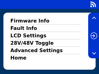
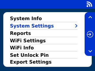
Basic Menu
Display the current Firmware installed on the VCLX NM2.
In case of any Fault, the relevant info will be displayed.
Adjust the brightness of the LCD screen, as well as adjusting the "Idle Off" settings
Toggle the voltage from 28v to 48V, or vice versa, of the 3-PIN XLR output.
Advanced Settings
Entering the Advanced Settings of the VCLX NM2. A Pin is required to access this area.
Home
Brings you back to the home-screen.
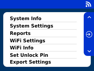
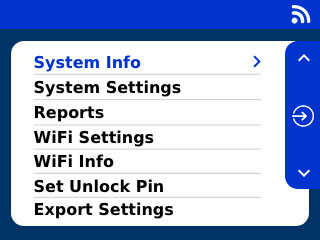
Advanced Menu
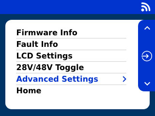
View your System Info like Serial Number, FCC, Health and Cycles.
Enable/disable the users’ ability to toggle between 28/48V in the ‘Basic Menu’. If this feature is disabled, then the unit will only have a 28V output.
Generate Reports and load them either on a USB drive or load them to you FTP destination.
Enable or disable the Wifi on your Battery
View the current status of the Wifi connection, including the FTP details and info about the last sync.
Set your unlock Pin for your VCLX NM2
Export all settings from your VCLX NM2, to load them onto another VCLX NM2
Start the "Built in self test" and save the results on a USB drive
Back
Sends you back to the Basic Menu
Home
Brings you back to the home-screen.
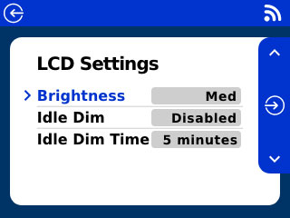
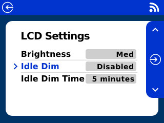
LCD Settings
Adjusting LCD brightness and Idle Dim Settings
To enter the LCD setting, press the settings button  on the home screen. Navigate to LCD Settings and press the enter button


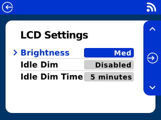
Adjusting LCD brightness
Select the value of the Brightness item by using the up
 and down
  buttons and confirm the selection with the enter button
 The value field will now show a blinking background to indicate the selection. Now use the up
or down button to choose between four values (Low, Med, High and Max).Confirm your selection with the enter button
Tip
On the home screen you can long-press the up and down buttons to adjust the LCD brightness.
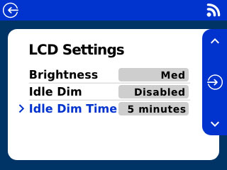
Idle Settings
Enable or Disable the Idle Dim as well as setting the Idle Dim time
To enable or disable the Idle Dim, select the value of the Idle Dim item by using the up
and down buttons. Confirm the selection with the enter button The value field will now show a blinking background to indicate the selection. Now use the up
or down buttons to enable or disable the Idle Dim.You can choose the Idle Dim time by selecting the value of the Idle Dim Time item by using the up
and down buttons. Confirm the selection with the enter button The value field will now show a blinking background to indicate the selection. Now use the up
and down buttons to select your Idle Dim time. Confirm your selection with the enter button
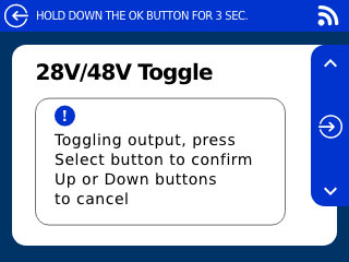
Switch from 28V to 48V
To allow the 3-Pin XLR port to output 28V or 48V.
Warning
Unplug any 3-Pin XLR device before performing the Voltage switch to avoid damage.
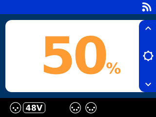
The home screen displays the current voltage used by the 3-Pin XLR output next to the icon
 . To perform the toggle enter the settings menu by pressing the settings button and using the up and down buttons to navigate to the 28V/48V Toggle menu item. Confirm you selection with the enter button

To perform the voltage toggle press the enter button
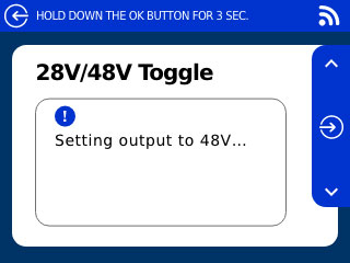
or use the up and down buttons to cancel.After confirming the toggle the toggle will start and will be completed within a couple of seconds.
The new output voltage for the 3-Pin XLR will now be displayed next to its icon
.

To toggle back to the previous output voltage, perform the same procedure.
Note
This feature can be enabled/disabled through the System Settings in the Advanced Menu.
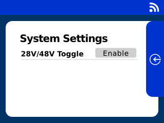
When the “28V/48V Toggle” setting is Enabled, a new option is located under the Basic Settings, “28V/48V Toggle”. The “28V/48V Toggle” setting persists through power cycle, but the VCLX NM2 will always be set to 28V when powered up.
PIN Code
Advanced Settings are only available for the owner of the battery. To secure them you will need a PIN code to access those.
To set the unlock PIN Code you will need to access the advanced settings. Press the settings button
on the home screen to access the basic settings. Navigate to "Advanced Settings " by using the up and down buttons and confirm your selection with the enter button .
To access the advanced settings you will need your PIN code. The factory standard PIN Code is 0000. Select the numbers by using the up
and down buttons and confirming each number with the enter button Tip
After 30 seconds, you will automatically come back to the home screen if no buttons are pressed.
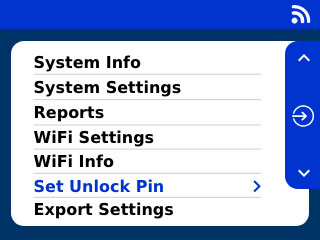
In the Advanced Settings menu select "Set Unlock Pin" by using the up
and down buttons and confirm with the enter button 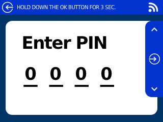
Use the up
and down buttons to select a number from 0-9 and confirm each number by the enter button . To cancel to process press and hold the enter button for 3 seconds.
 If the PIN CODE has been forgotten, please contact customer support.
How to setup WiFi
Use WiFi to upload reports to a FTP Server or to use the Anton/Bauer Fleet Management.
To use the Wifi Module in the VCLX NM2, you will need to create a config file which contains your WiFi information, as well as FTP details for your report upload. Follow these steps to generate the file and load into you VCLX NM2. You will need a Computer and USB drive (Ensure the USB drive is formatted to use FAT32 file system) to complete this procedure.
Start by enabling WiFi through the advanced settings menu (To access the advanced settings menu, follow step 1 and 2 on the PIN Code Settings) and select the WiFi settings by using the up
and down buttons, confirm the selection with the enter button .Use the up
or down button to enable the the WiFi module. Confirm the selection with the enter button 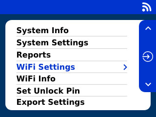

Now turn off the VCLX NM2 by pressing the Power-on button.
Visit vclx.antonbauer.com and login using the following credentials.
User: VCLXNM2
Password: AntonBauer155
Now fill in your WiFi information and FTP Details and press "Generate File".
Your Information will not be saved and all password details are fully encrypted.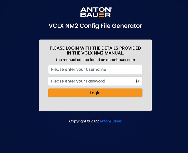

You will receive a vclx.ini file. Please place it onto the root folder of a USB drive.
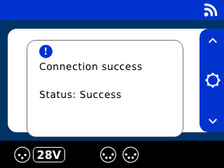
Insert the USB drive into the USB Port of the VCLX NM2. Power on the battery until the import process is complete. The Battery will try to login to your WiFi with the provided information, and will show a status screen after the connection attempt is complete. If the connection wasn't successful, then please repeat step 4 - 6 again.
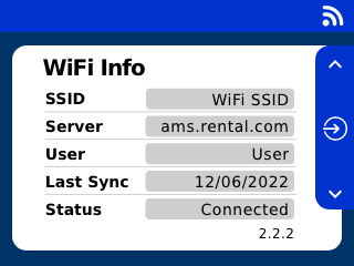
To check the WiFi Status, navigate to the advanced settings menu (as in Step 1) and navigate to the WiFi Info menu item by using the up
and down buttons and confirm the selection with the enter button You will receive information about the SSID which the battery is connected to, as well as the FTP Server info. The WiFi Info screens also shows the last Sync informations and the current WiFi status. To go back to the advanced setting menu, press the back button


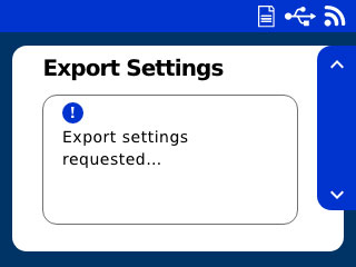
Export Settings
You have the option to configure one VCLX NM2 and apply those same settings onto other VCLX NM2 Batteries.
Before you can start, plug-in a a USB drive into the USB port of the VCLX NM2.
Navigate to the advanced settings menu (To access the advanced settings menu, follow step 1 and 2 on the PIN Code Settings) and select the "Export Settings" menu item by using the up
and down buttons, confirm the selection with the enter button 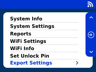
The export will start immediately and will show a success message when complete.
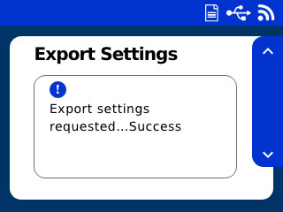
Now you can unplug your USB drive and use it to import the settings to other VCLX NM2 Batteries. Simple turn off the other VCLX NM2 and startup again with the USB drive plugged in, the import process will start automatically.
Generate Reports
The VCLX NM2 can generate reports about the health status of the battery. You can save a report on a USB drive or using Wifi. If you use the Wifi Settings , a report will be generated and uploaded to your FTP server. Note that Wifi is disabled by default and a USB drive is required to configure the wifi settings. If the VCLX NM2 is not able to connect to a network, the Wifi module will enter low power mode. This ensures that Wifi will save battery life and not cause interference when used out on set.
Before you can start, plug-in a a USB drive into the USB port of the VCLX NM2
Navigate to the advanced settings menu (To access the advanced settings menu, follow step 1 and 2 on the PIN Code Settings) and select the "Reports" menu item by using the up
and down buttons, confirm the selection with the enter button 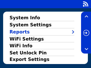
By using the up
and down buttons you change the data type which should be exported, define the number of weeks to be exported and the export destination. Confirm your selection with then enter button .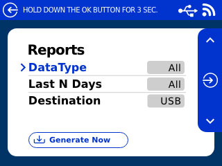
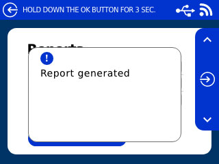
Now navigate to the "Generate Now" button and confirm with the enter button
. And your report will be generated. A success message will appear as soon as the upload is complete.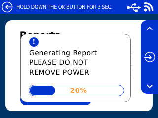
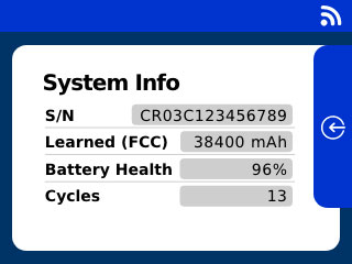
System Info
The VCLX NM2 can give you vital insight about the current health and status of the battery. Following information will be displayed:
Serial Number
Discharge Capacity - Is the total amount of energy you can extract from the fully charged state until empty.
Battery Health (%) - Accurately shows the charged % of the battery.
Cycles - The number of charge and discharge cycles
To enter the system info screen navigate to the advanced settings menu (To access the advanced settings menu, follow step 1 and 2 on the PIN Code Settings) and select the "Systems info" menu item by using the up
and down buttons, confirm the selection with the enter button .To leave the system info screen, simple press the back button
Warnings and Errors
Notification | Classification | Solving |
|---|---|---|
Charge Error | Error | If a charging error, then remove charger and re-insert. Power Cycle Unit To Clear Error. If fault continues call service. |
Charge Warning | Warning | Charging Paused - Allow Time For Pack(s) To Cool. Charging Will Resume Automatically |
Discharge Error | Error | Remove Devices, Power Cycle Unit To Clear Error. |
Invalid Pack Error | Error | Call For Service |
Temperature Error | Error | Call For Service |
XLR Load Error | Error | Reconnect devices one at a time and use the visual output connector warning on the display to see if you are overloading that XLR output. If fault continues call service. |
XLR Current Warning | Warning | You are within 90% of the max load for this output. |
Max Load Warning | Warning | Total System Load Exceeding 700W Rating, Please Remove Devices. If devices aren't removed the unit may shut down to protect itself. |
How to update firmware
We will inform VCLX NM2 customers about new firmware updates, alternatively you can download the latest firmware from the Anton/Bauer website - antonbauer.com/downloads
View the current Firmware
When powering the VCLX NM2, the Firmware is displayed on the loading screen. Alternative you can view the current Firmware in the basic menu.
To enter the Firmware info, press the settings button
on the home screen. Navigate to "Firmware Info" and press the enter button .You will see the current Firmware Part Number as well as the Revision.
To come back, simple press the back button
.
Follow these steps to update the Firmware on the VCLX NM2. You will need a Computer and USB drive (Ensure the USB drive is formatted to use FAT32 file system) to complete this procedure.
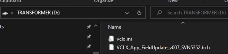
Download the Firmware and Extract the contents of the zip file.
Copy and paste the contents of the zip file to the root directory of a USB flash drive.
Power OFF the VCLX NM2.
Insert the USB flash drive into the VCLX NM2.
Plug the charger into the VCLX NM2 and turn it on.
Important
Keep the power supply plugged in during the update process.
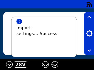
The VCLX will power up, and a couple of message boxes will be shown: Import Settings Success & Firmware Update in progress.
When the progress bar reaches 100%, the VCLX will reboot, and the screen will go blank for 10 to 20 seconds.
The VCLX will reboot again, and the splash screen will be seen, followed by the home screen.
The update is complete, and it is now safe to remove the power supply.
Power cycle the VCLX (remove charger and turn button OFF/ON).
BIST results and troubleshooting
Built In Self Test
The Build in Self Test will run through ten different tests to check the health of the Battery and its functionality. After the test, the result will be saved onto a USB drive for you to review. Find below a summary of the individual tests.
Test Case | Purpose | User Interaction |
|---|---|---|
Key Inputs | Check up/center/down | Yes |
LCD Backlight | Check brightness | Yes |
WiFi | Check connectivity to module (not WiFi network) | No |
XLR Breakers | Check internal switches | N |
Active Faults | Check if any faults are active | No |
Idle Current | Check system idle current | Yes |
Charge Current | Check charging current | Yes |
Temperature | Check cell pack temperatures | No |
Overall Health | No | |
Fixed Load | Check XLR connectors | Yes |
Before you can start, plug-in a a USB drive into the USB port of the VCLX NM2 (Ensure the USB drive is formatted to use FAT32 file system).
To enter the BIST navigate to the advanced settings menu (To access the advanced settings menu, follow step 1 and 2 on the PIN Code Settings) and select the "BIST" menu item by using the up
and down buttons, confirm the selection with the enter button .Confirm with the enter button
to run the report.After the self test is complete, the report will be loaded to you USB drive (vclx.bist)
You can use a "vclx.ini" file on a USB drive to trigger the build in self test. You will need a Computer and USB drive (Ensure the USB drive is formatted to use FAT32 file system) to complete this procedure.
Use a Text Editor and paste the following code.
; VCLX config file1
[BIST]2
OverallHealth = run3
ActiveFaults = run
IdleCurrent = run
WiFi = run
XLRBreakers = run
KeyInputs = run
LCDBacklight = run
ChargeCurrent = run
FixedLoad = skip
execute = yes4
Save this file as "vclx.ini" onto the USB drive.
Power ON the VCLX NM2 and if you enabled the autostart, then the BIST will run after startup automatically. After the self test is complete, the report will be loaded to you USB drive (vclx.bist).