VCLX Operation
Software Interface Layout
1 | Fuel gauge (Shows % when no device is attached; shows remaining runtime in hours and minutes when device is attached) |
2 | Report Indicator |
3 | USB Indicator |
4 | Wifi Status |
5 | Up Button - Increase a value or navigate Upwards |
6 | Settings / Enter / Save / Back Button |
7 | Down Button - Decrease a value or navigate Downwards |
8 | 4-Pin XLR-R Output Status |
9 | 4-Pin XLR-M Output Status |
10 | 3-Pin XLR Output Voltage (28V or 48V) |
11 | 3-Pin XLR-L Output Status |
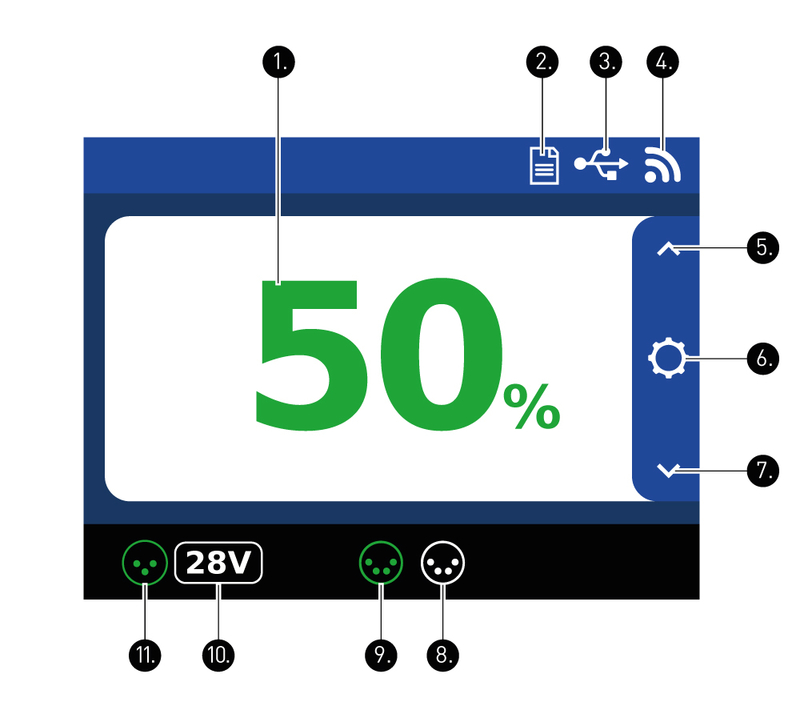
Icon/Symbol explanation


Basic Operation
Turning on and powering a device
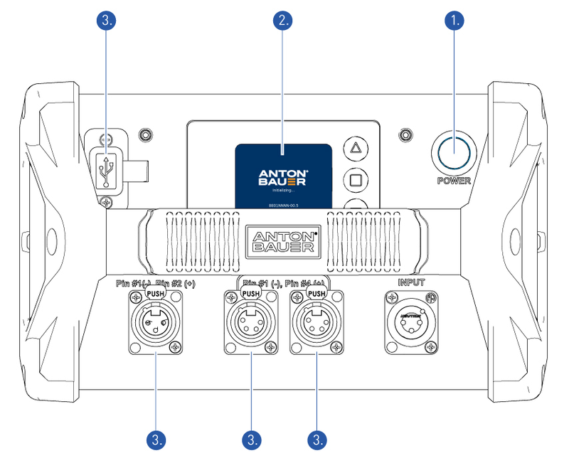
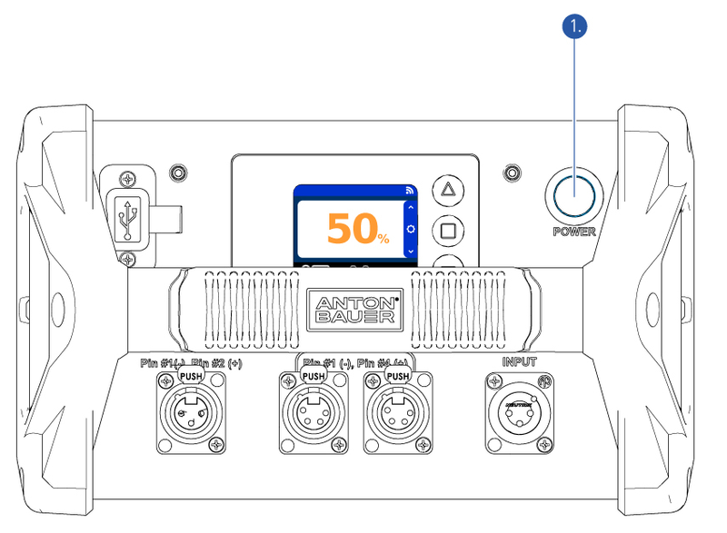
To turn on the VCLX NM2 press the Power-on button. (1) You will see a solid blue light around the Power-on button.
The loading screen (2) will show a Anton/Bauer Logo with the current Firmware listed below. After a few second the home screen will appear.
Now use any of the four outputs (3) to power any device. As soon as a draw is attached to the VCLX NM2, the output icon will turn green and the remaining runtime will show in minutes on the home screen.
To turn off the VCLX NM2 simple press the Power-on button (1).
Status screens
The VCLX NM2 can display the current System Voltage (V), Current (A) and Power (W) for each XLR output.
On the home screen use the up
or down
buttons to access the status screens. Each screen will show you in real-time the current System Voltage (V), Current (A) and Power (W) for each XLR output
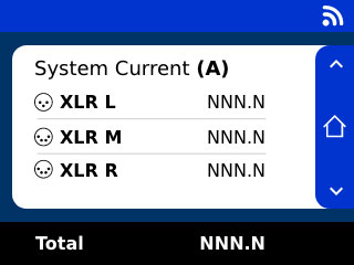
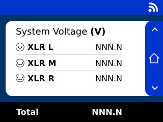
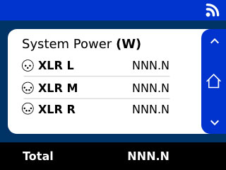
To come back to the home screen, simple press the home button
or toggle through the up or down buttons until you are back to the home screen.